Examples#
Examples show how to set up MCUViewer with different probes.
Raspberry Pi debug probe example - Var Viewer#
Raspberry Pi debug probe is not natively supported by MCUViewer. This means that we need a GDB server to connect to it. In this example we will use OpenOCD with an example project for Raspberry Pi Pico rp2040.
Create a new Raspberry PI Pico project in VScode
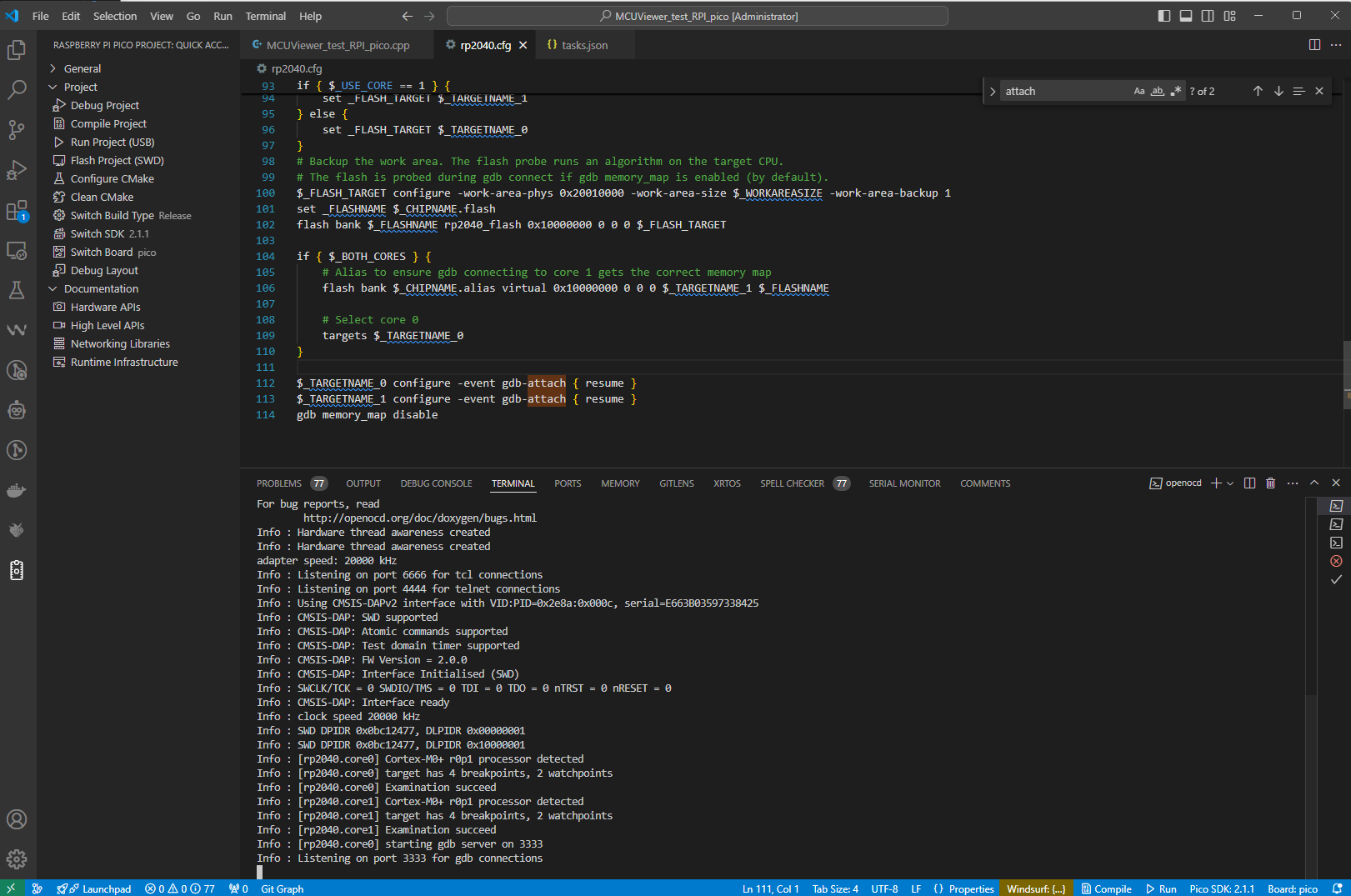
Copy the interface/rp2040.cfg to the project folder. Add the following lines at the end of the file:
$_TARGETNAME_0 configure -event gdb-attach { resume }
$_TARGETNAME_1 configure -event gdb-attach { resume }
gdb memory_map disable
These will ensure we will not get a halt when connecting to the target.
Add some global variable to your project that you want to see in MCUViewer. In this example we will use two global variables:
float x
float sin_x;

...

while (true)
{
    x += 0.01f;
    sin_x = sin(x);

    sleep_ms(1);
}
this way we should be able to see a sine wave when we import sin_x in MCUViewer.
Compile and download the firmware using VScode. For easier download while using MCUViewer please follow the instructions in the Flashing the firmware section.
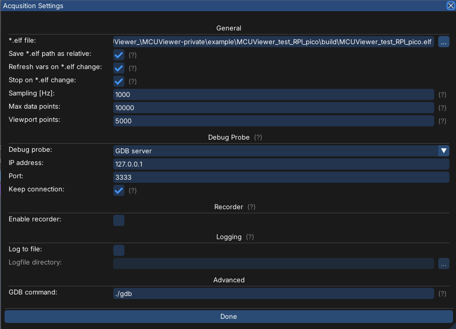
Start a new MCUViewer project, select the *.elf file and select GDB server as debug probe. Put the ip address 127.0.0.1 and port 3333 in the GDB server settings and close the window.
Import the ‘sin_x’ variable and drag and drop it onto the plot.
Run OpenOCD in terminal window. Example command could look like this:
openocd -f interface/cmsis-dap.cfg -f ./rp2040.cfg -c "adapter speed 20000"
Note that we are using the copy of target config from step 1.This command should connect the probe to the target without halting it.
Start the acquisition in MCUViewer - you should see the sine wave.
Flashing the firmware#
Flashing each new firmware can be made easy by creating a custom task in the tasks.json file - this way we will attach to the openOCD that we’ve run previously and download the compiled firmware with a single click.
Add the following task to the tasks.json file:
        {
            "label": "Flash ELF with OpenOCD",
            "type": "shell",
            "command": "python",
            "args": [
                "${workspaceFolder}/flash_openocd.py",
                "your_elf_file_path",
                "--host",
                "localhost",
                "--port",
                "4444"
            ],
            "group": {
                "kind": "build",
                "isDefault": true
            },
            "presentation": {
                "reveal": "always",
                "panel": "shared"
            },
            "problemMatcher": []
        }
Modify “your_elf_file_path” with the full path to your ELF file. This task will simply run a python script. Let’s now create the script.
Add the following python script to the root of the project:
import telnetlib
import time
import argparse
import os
import sys

# --- Argument parsing ---
parser = argparse.ArgumentParser(description="Flash ELF file to target via OpenOCD Telnet")
parser.add_argument("firmware", help="Path to the .elf firmware file")
parser.add_argument("--host", default="localhost", help="OpenOCD Telnet host (default: localhost)")
parser.add_argument("--port", type=int, default=4444, help="OpenOCD Telnet port (default: 4444)")

args = parser.parse_args()

# --- File check ---
if not os.path.isfile(args.firmware):
    print(f"Error: File not found: {args.firmware}")
    sys.exit(1)

# --- Telnet command sender ---
def send_cmd(tn, cmd, wait=0.5, expect=b'>'):
    tn.write(cmd.encode('ascii') + b"\n")
    time.sleep(wait)
    print(tn.read_until(expect, timeout=5).decode('ascii'))

# --- Main session ---
with telnetlib.Telnet(args.host, args.port) as tn:
    send_cmd(tn, "halt")
    send_cmd(tn, f"program {args.firmware} verify", wait=2)
    send_cmd(tn, "resume")
    send_cmd(tn, "exit")
This script will connect to the openOCD session using telnet on port 4444, halt the target, program the new firmware, verify it and resume the target.
Select Terminal->run task “Flash ELF with OpenOCD” to flash the new firmware. Done!
Raspberry Pi debug probe example - Recorder#
Sometimes Variable Viewer sampling rate is not stable enough, especially when high sampling rates are needed. In such cases, it is better to use the Recorder module. More on the recorder module can be found in the Recorder section. In out case we’re going to call the recorderStep() function in a 50kHz interrupt handler.
Follow the steps from the previous section to have a working Variable Viewer module.
Copy the “Recorder” folder from the downloaded MCUViewer *.zip file to your project. The recorder module on the target side consists of three files:
recorder.c
recorder.h
recorderDefines.h
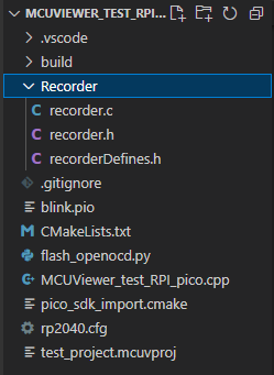
Add the recorder.c file and Recorder folder to your CMakeLists.txt file:
add_executable(MCUViewer_test_RPI_pico
        MCUViewer_test_RPI_pico.cpp
        Recorder/recorder.c                 # Recorder file
)
target_include_directories(MCUViewer_test_RPI_pico PRIVATE
        ${CMAKE_CURRENT_LIST_DIR}
        ${CMAKE_CURRENT_LIST_DIR}/Recorder  # Recorder folder
)
Add the recorder to your project (we need to call it periodically in a high priority interrupt handler with certain frequency, in our case 50kHz - every 20us)
#include "Recorder/recorder.h"

/* recorder interrupt handler */
void timer_irq_handler()
{
	// Clear the alarm
	hw_clear_bits(&timer_hw->intr, 1u << 0);
	// Schedule the next interrupt 20 µs from now
	uint64_t target = timer_hw->timerawl + 20;
	timer_hw->alarm[0] = (uint32_t)target;

	/* Call the recorderStep function */
	recorderStep();
}

/* recorder interrupt setup */
void init_timer_irq_50khz()
{
	// Choose alarm 0
	hw_set_bits(&timer_hw->inte, 1u << 0);						// Enable interrupt for alarm 0
	irq_set_exclusive_handler(TIMER_IRQ_0, timer_irq_handler);	// Set handler
	irq_set_enabled(TIMER_IRQ_0, true);							// Enable the interrupt in NVIC

	// Fire first interrupt 20 us from now
	uint64_t now = time_us_64();
	timer_hw->alarm[0] = (uint32_t)(now + 20);
}


int main()
{
    ...
    init_timer_irq_50khz();
    ...
    while(1)
    {
        ....
    }
}
Remember to modify the recorderDefines.h file to match your system configuration (buffer size, sampling frequency, etc.).
Compile and flash the project.
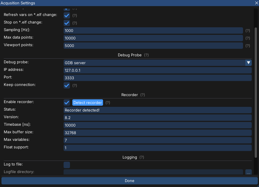
Open the MCUViewer and proceed to
Acquisition settingswindow. SelectEnable recordercheckbox and clickDetect recorderbutton.If the recorder is detected correctly there should be no errors, just a
Recorder detected!information with all fields filled in as in therecorderDefines.hfile.
Create new recorder group by right-clicking in the plot group tree area and select
New -> Recorder group.Import the ‘sin_x’ variable and drag and drop it onto the plot in the recorder group.
Start the acquisition and you should see the sine wave with much more detail and higher sampling rate.