C2000 and serial driver
C2000 is a very popular MCU family, especially in power electronics projects - unfortunately there is no API provided by Texas Instruments for the debug probes, so MCUViewer has a slightly different approach for reading data out of C2000 MCUs.
Serial driver setup
Instead of using only the debug probe, the MCUViewer needs an additional UART/RS485 connection to your PC. You can do it either by a dedicated UART to USB converter or use the debug probe’s serial port. The general approach is described in Serial Setup section, however here we will go through a simple C2000 example.
Hardware setup
In this tutorial we will be using a launchpad LAUNCHXL-F2800137 from Texas Instruments. To simplify the setup we will not be using an additional USB<>UART dongle, only the build-in one.
Software
We will be using Code Composer Studio and MCUViewer. You might also need a terminal program, such as RealTerm, to test the UART communication.
Project setup
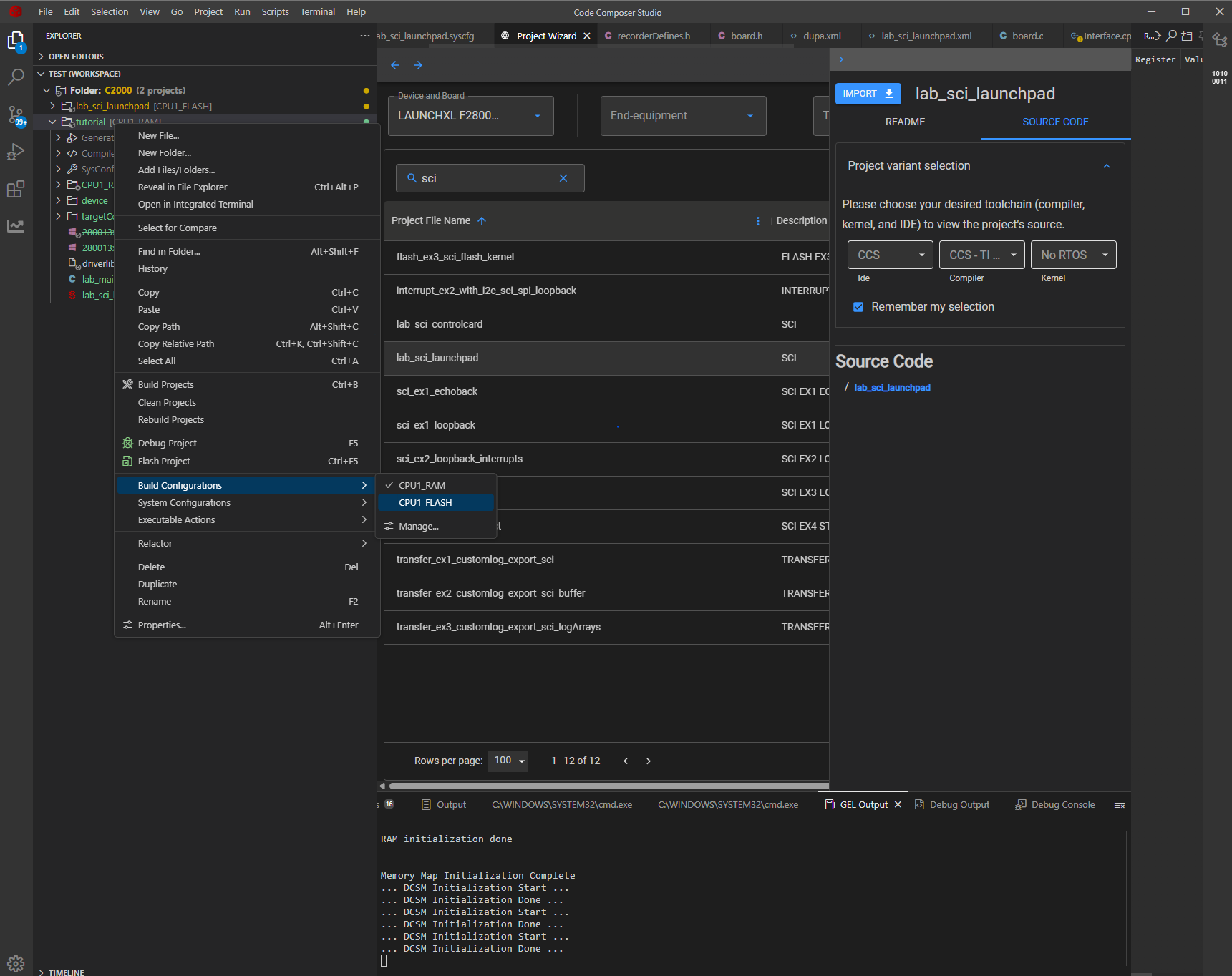
First we have to create a new project based on the launchpad board that we’ll be using. We can select “lab_sci_launchpad” as the starting example.
Let’s change to FLASH build configuration to make our executable persistent:
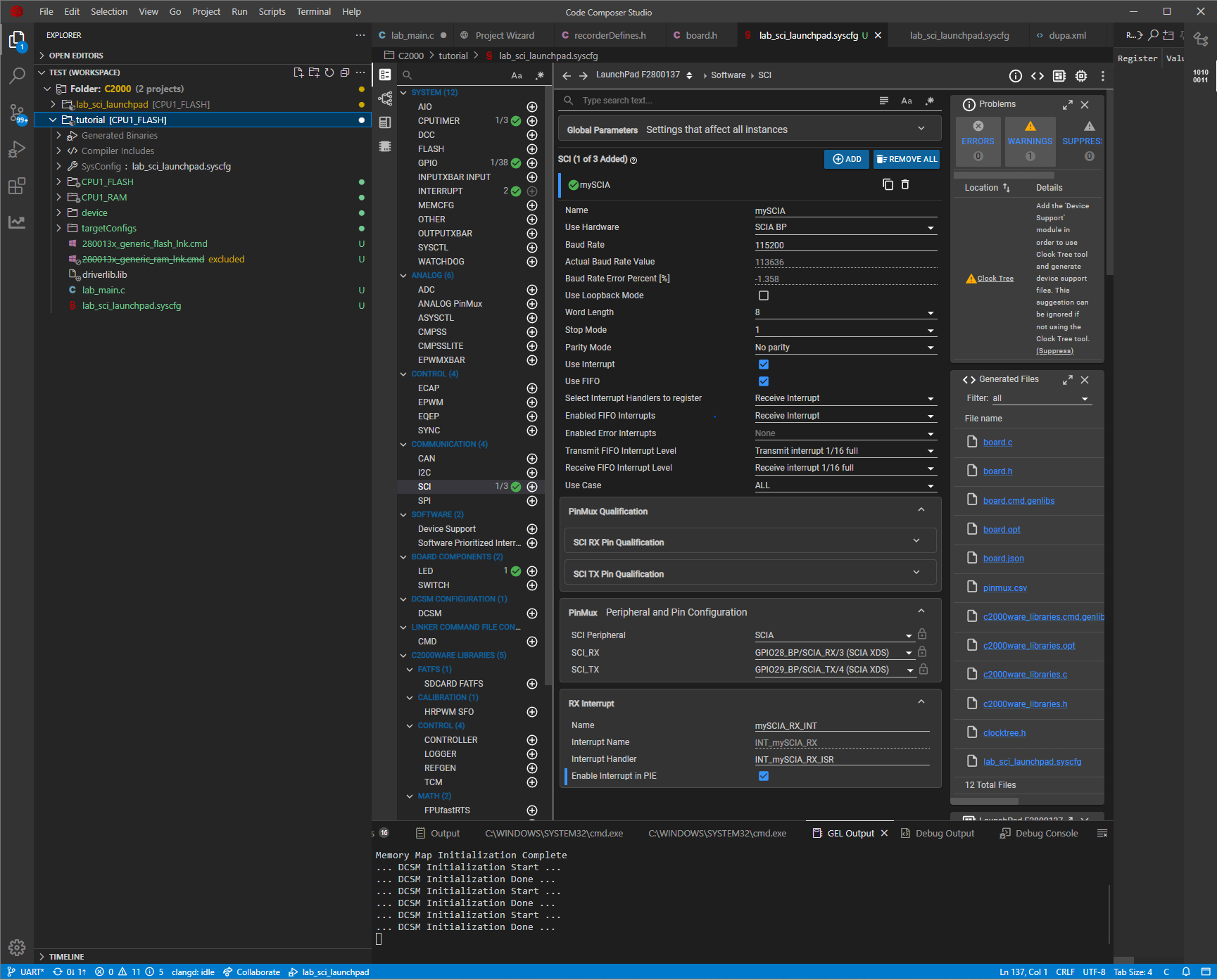
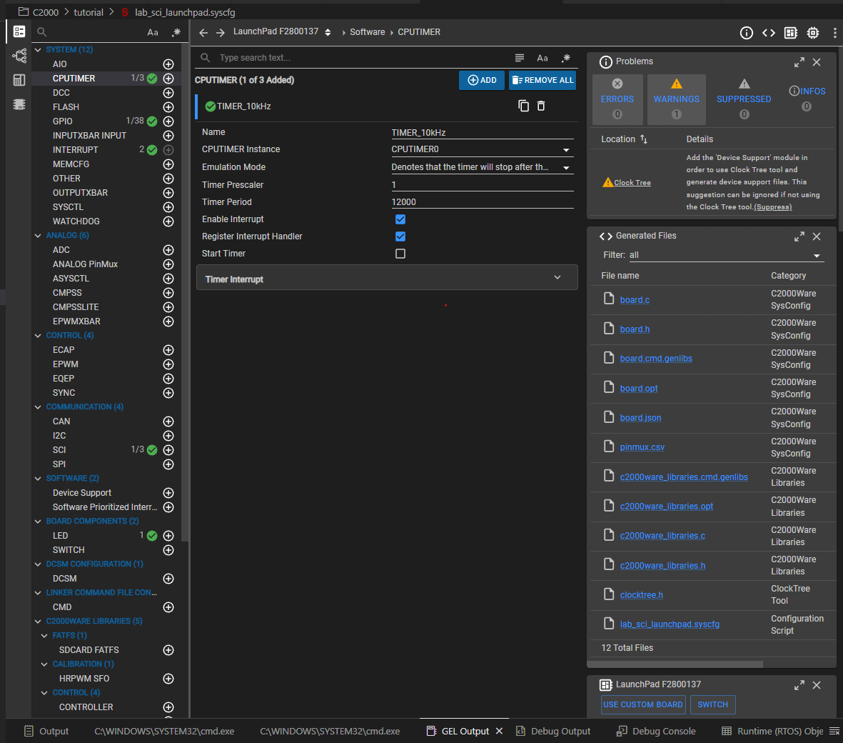
And we can move on to the sysconfig setup - there we need to fill all the required fields as shown in the picture below (note that we need the RX interrupt):
Next, we need to replace the “lab_main.c” file with the following content:
#include <stdint.h>
#include "board.h"
#include "device.h"
#include "driverlib.h"

__interrupt void INT_mySCIA_RX_ISR(void);

void main(void)
{
    Device_init();
    Interrupt_initModule();
    Interrupt_initVectorTable();

    Device_initGPIO();

    Board_init();

    EINT;
    ERTM;

    for (;;)
    {
    }
}

__interrupt void INT_mySCIA_RX_ISR(void)
{
    /* read from FIFO */
    char rxChar = SCI_readCharBlockingFIFO(mySCIA_BASE);
    /* clear interrupt flags */
    SCI_clearInterruptStatus(mySCIA_BASE, SCI_INT_RXFF);
    Interrupt_clearACKGroup(INT_mySCIA_RX_INTERRUPT_ACK_GROUP);
    /* send back the character */
    SCI_writeCharArray(mySCIA_BASE, &rxChar, 1);
}
This code is essentially a loopback test - you can also include an initial message to test the transmission alone. In our case it was tested with RealTerm:
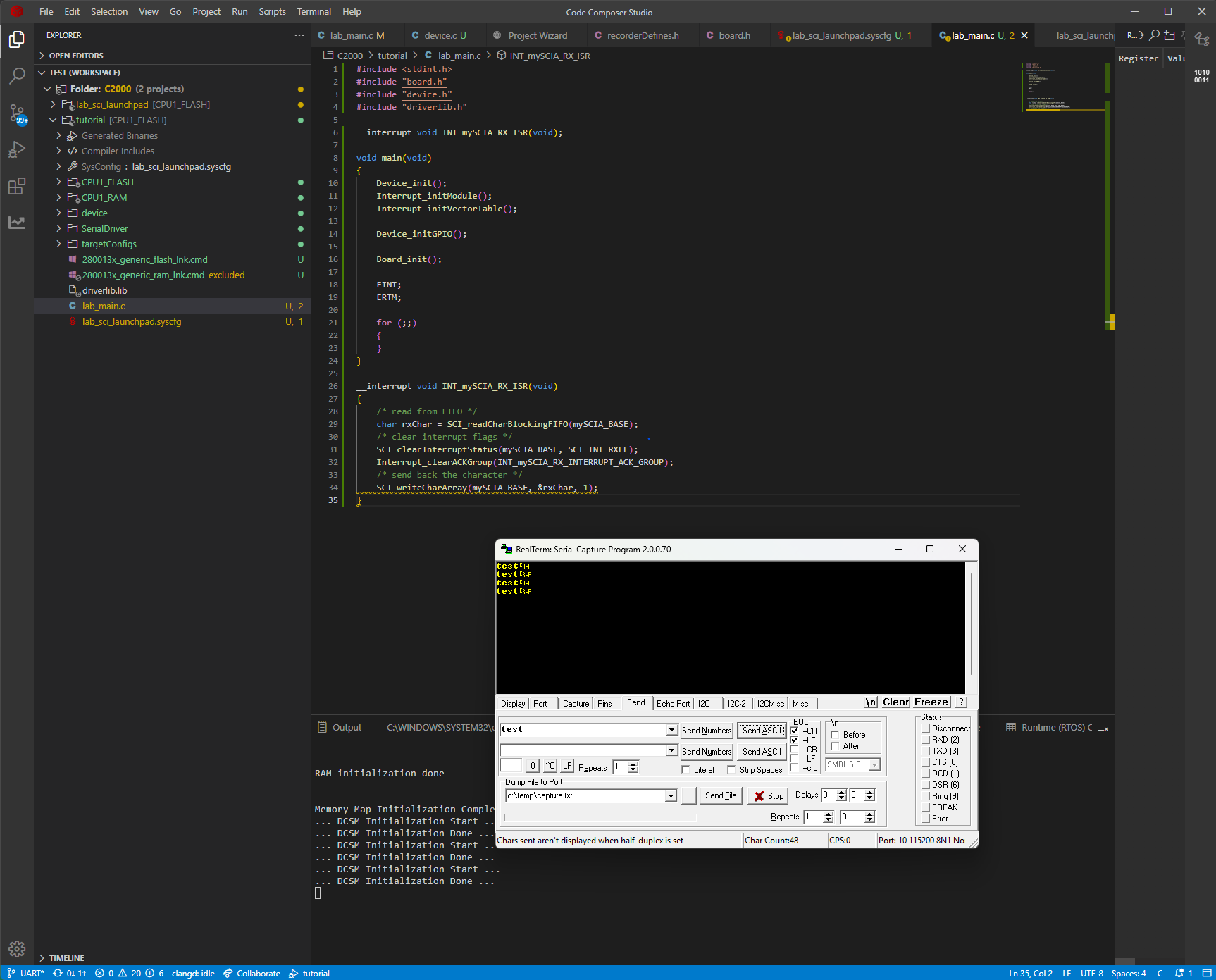
Great - now we are sure the UART communication works and we can move on to adding the serial driver.
Adding Serial driver
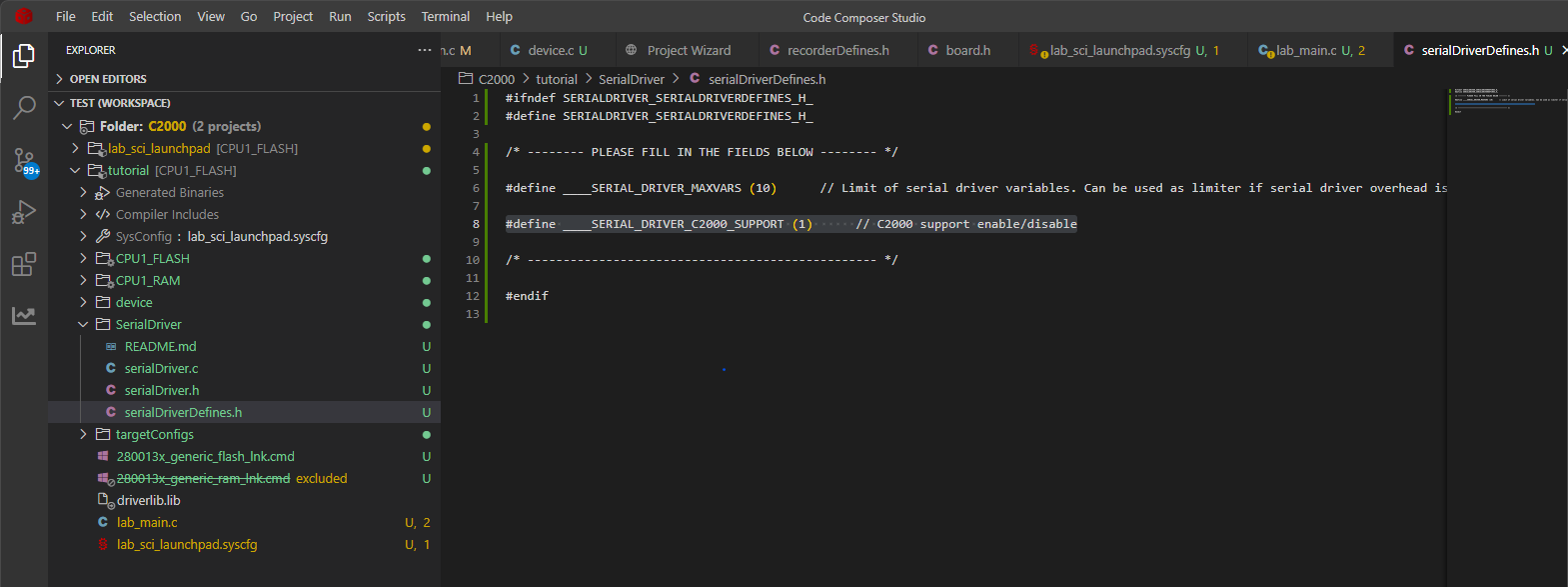
Adding the serial driver is pretty straightforward - simply copy the serialDriver folder to the project and adjust the serialDriverDefines.h file to match your system configuration. The serialDriver folder can be downloaded together with MCUViewer executable here.
In our case it is essential to remember about the ____SERIAL_DRIVER_C2000_SUPPORT macro.
Now let’s modify our code, by implementing the serial driver send and receive functionalities (plus some test sine wave):
#include <stdint.h>
#include "board.h"
#include "device.h"
#include "driverlib.h"
#include "SerialDriver/serialDriver.h"
#include <math.h>

__interrupt void INT_mySCIA_RX_ISR(void);

float test_x = 0.0f;
float test_sin = 0.0f;

void main(void)
{
    Device_init();
    Interrupt_initModule();
    Interrupt_initVectorTable();

    Device_initGPIO();

    Board_init();

    EINT;
    ERTM;

    for (;;)
    {
        test_sin = sinf(test_x);
        test_x += 0.00001f;

        if(test_x > 6.28f)
            test_x = 0.0f;
    }
}

/* serial driver send data function - called whenever there's data to send */
void serialDriverSendData(uint16_t* buf, uint16_t size)
{
    SCI_writeCharArray(mySCIA_BASE, buf, size);
}

__interrupt void INT_mySCIA_RX_ISR(void)
{
    /* read from FIFO */
    char rxChar = SCI_readCharBlockingFIFO(mySCIA_BASE);
    /* clear interrupt flags */
    SCI_clearInterruptStatus(mySCIA_BASE, SCI_INT_RXFF);
    Interrupt_clearACKGroup(INT_mySCIA_RX_INTERRUPT_ACK_GROUP);
    /* call serial driver function */
    serialDriverReceiveByte(rxChar);
}
Great - now we’re ready to test the solution.
First Acquisition
Before we can import the variables into MCUViewer it is essential to switch to *.elf file as output of our linking process. Right click on the project and select properties. There navigate to the linker tab and change the output to *.elf.
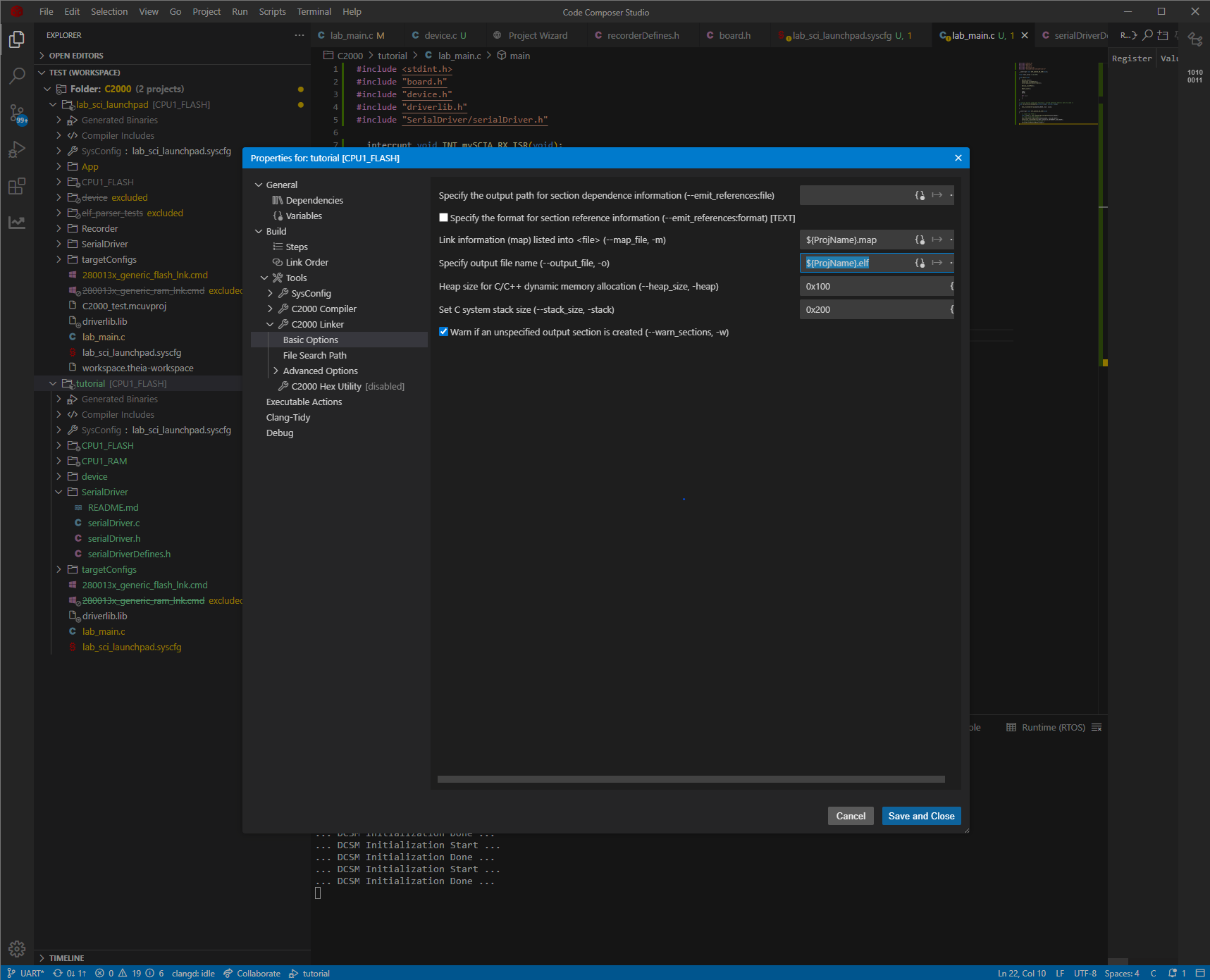
Now, after compilation the *.elf file should be generated - in our case in CPU1_FLASH/ directory.
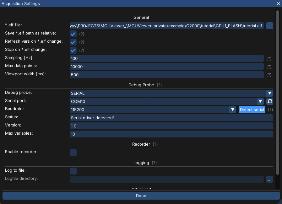
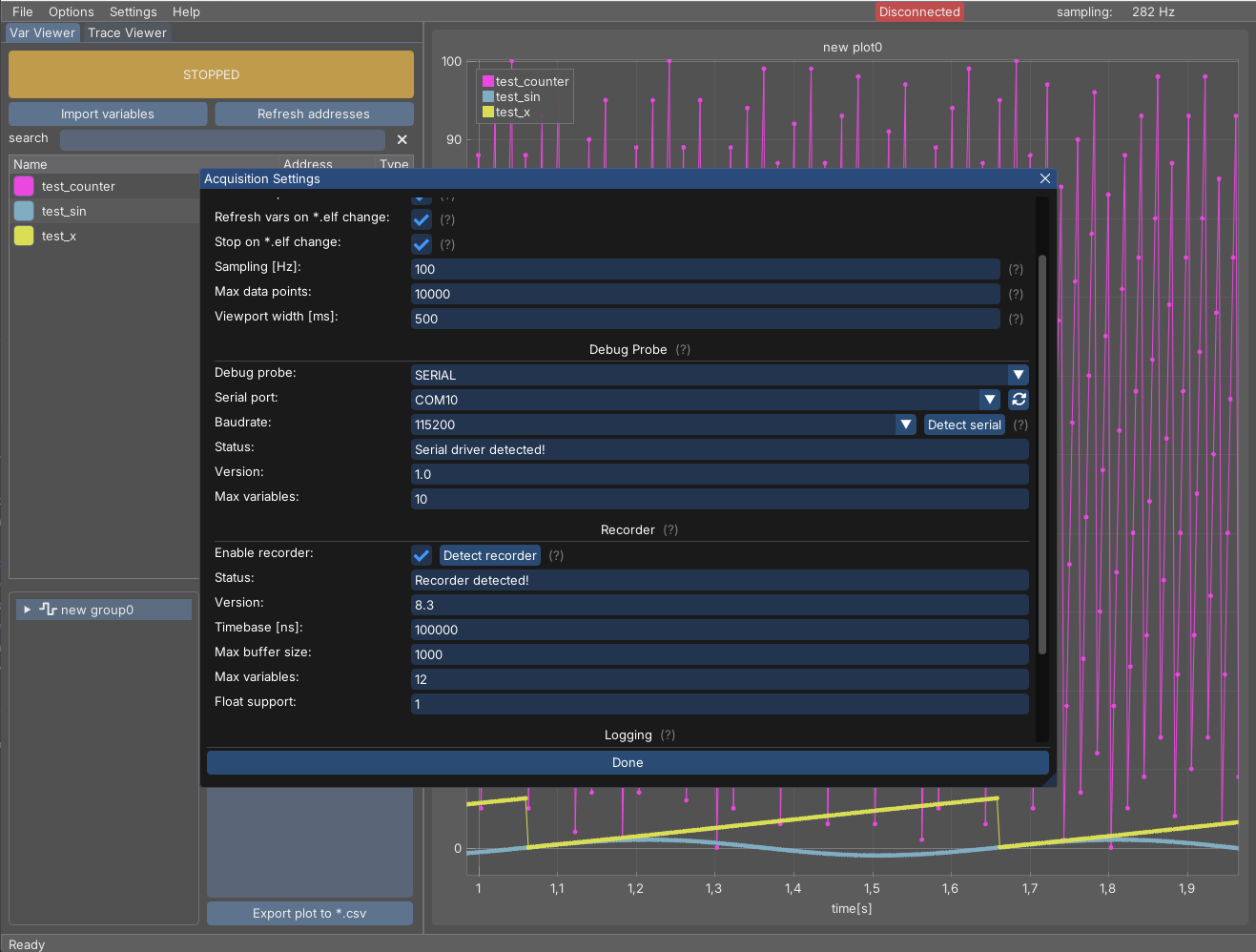
Let’s launch MCUViewer, select Options->Acquisition and select the *.elf file. Next, switch the debug probe to SERIAL, and fill in the port and baudrate values. Make sure the port is free (not used by other software such as UART terminal), and click Detect serial button. You should see the serial driver version and max variables in the status text box as in the picture below:
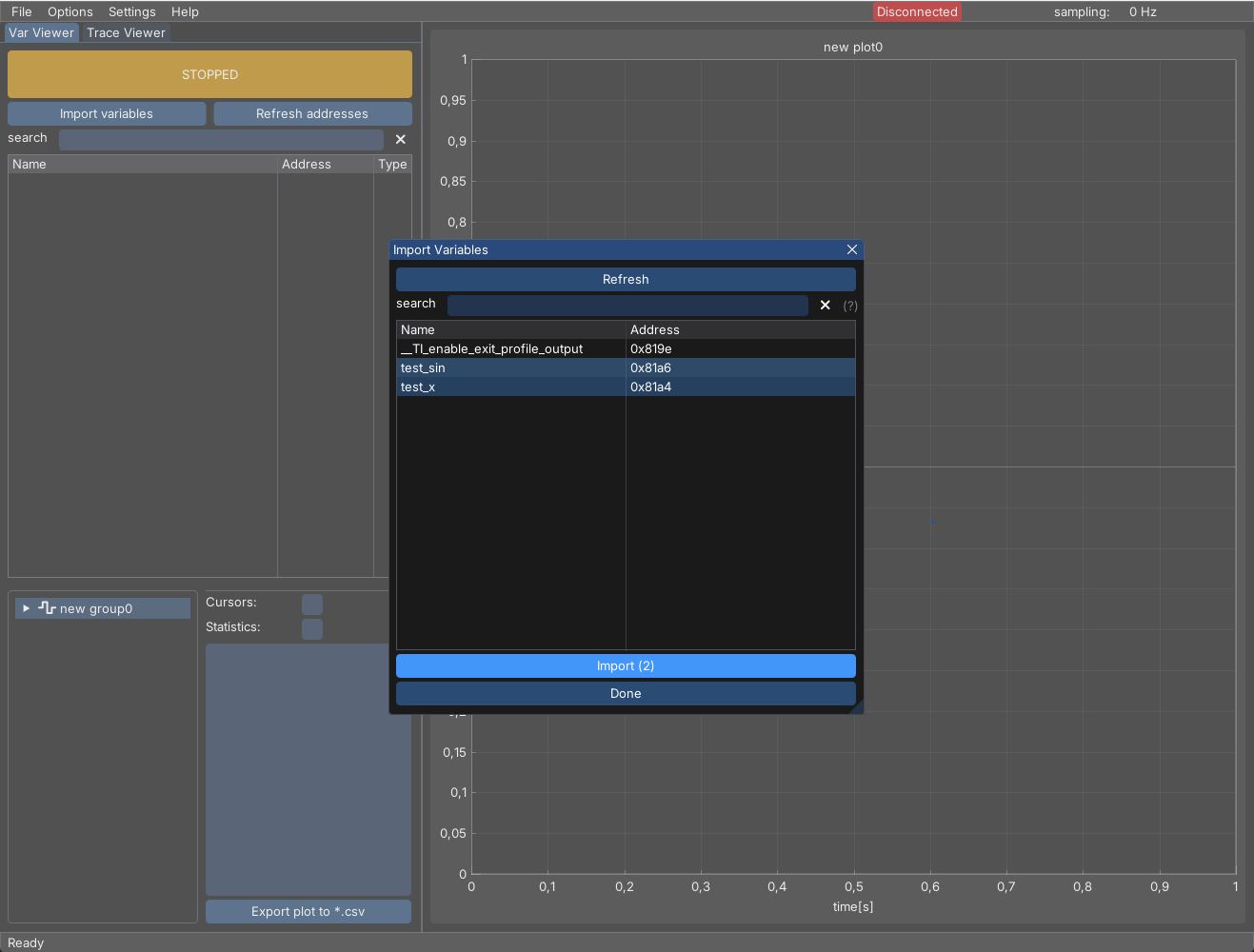
This means the serial driver is working and now it’s ready to visualize our data. Select ‘Import Variables’ and pick ‘test_x’ and ‘test_sin’ variables.
Drag and drop them on the plot and select the start button. You should see the values being plotted as in the picture below:
In case of any issues please visit the Variable Viewer page and visit the FAQ section.
Adding Recorder
The recorder module is useful when the UART communication (or generally the communication with the target MCU) is slow and you want to visualize high frequency data. Let’s add a 10kHz interrupt to our code so that we can see the issue:
#include <math.h>
#include <stdint.h>

#include "SerialDriver/serialDriver.h"
#include "board.h"
#include "device.h"
#include "driverlib.h"

__interrupt void INT_mySCIA_RX_ISR(void);
__interrupt void INT_TIMER_10kHz_ISR(void);

float test_x = 0.0f;
float test_sin = 0.0f;
int32_t test_counter = 0;

void main(void)
{
    Device_init();
    Interrupt_initModule();
    Interrupt_initVectorTable();

    Device_initGPIO();

    Board_init();

    EINT;
    ERTM;

    CPUTimer_startTimer(TIMER_10kHz_BASE);

    for (;;)
    {
        test_sin = sinf(test_x);
        test_x += 0.00001f;

        if (test_x > 6.28f)
            test_x = 0.0f;
    }
}

void INT_TIMER_10kHz_ISR(void)
{
    test_counter++;

    if (test_counter > 100)
        test_counter = 0;

    Interrupt_clearACKGroup(INT_TIMER_10kHz_INTERRUPT_ACK_GROUP);
}

/* serial driver send data function - called whenever there's data to send */
void serialDriverSendData(uint16_t* buf, uint16_t size)
{
    SCI_writeCharArray(mySCIA_BASE, buf, size);
}

__interrupt void INT_mySCIA_RX_ISR(void)
{
    /* read from FIFO */
    char rxChar = SCI_readCharBlockingFIFO(mySCIA_BASE);
    /* clear interrupt flags */
    SCI_clearInterruptStatus(mySCIA_BASE, SCI_INT_RXFF);
    Interrupt_clearACKGroup(INT_mySCIA_RX_INTERRUPT_ACK_GROUP);
    /* call serial driver function */
    serialDriverReceiveByte(rxChar);
}
Now when we try to visualize the test_counter in VarViewer we can clearly see the issue:
The counter signal is too fast and aliasing occurs - we can no longer trust this output. Now’s the time to try visualizing it using the recorder module.
The integration is described in the Recorder section - basically we need to copy the Recorder directory to the project directory (similar to the serial driver) and modify the recorderDefines.h file to match our system configuration.
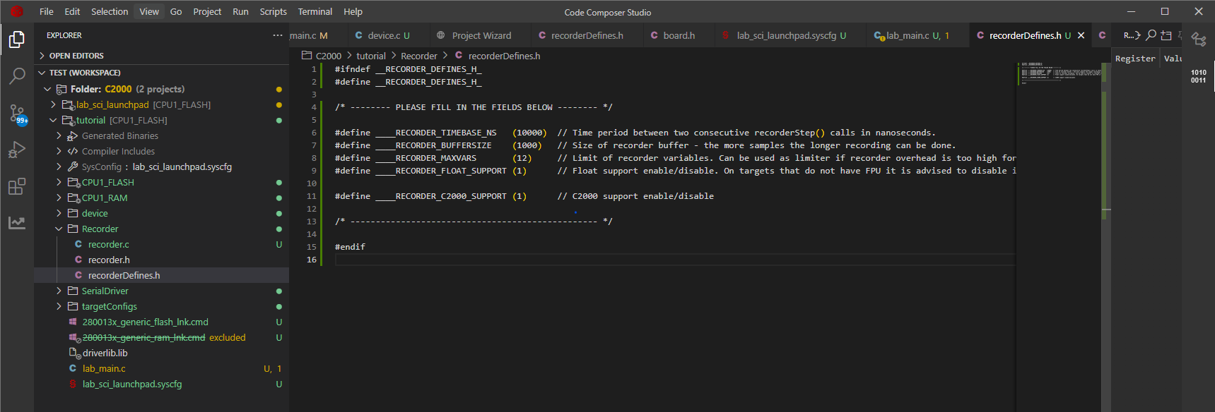
The recorder works by sampling selected variables at regular intervals - usually from within a high frequency interrupt - out 10kHz interrupt fits this requirements perfectly. Let’s add the #include "Recorder/recorder.h" include and recorderStep() call inside the interrupt like so:
void INT_TIMER_10kHz_ISR(void)
{
    test_counter++;

    if (test_counter > 100)
        test_counter = 0;

    Interrupt_clearACKGroup(INT_TIMER_10kHz_INTERRUPT_ACK_GROUP);

    recorderStep();         // <---- recorder call
}
Now when we have to compile and flash the project to our target MCU. The next step is to check if recorder works correctly - go to Options->Acquisition and check Enable Recorder checkbox. Click Detect recorder button. If the recorder is detected correctly there should be no errors, just a Recorder detected! information with all fields filled in as in the recorderDefines.h file.
Now create a new group of recorder type and drag and drop the test_counter variable into it.
After clicking the Start button the plot should look like in the picture below, showing us all the signal details with no aliasing:
In case of any issues please visit the Recorder page and visit the FAQ section.